Breakaway Wiring Diagram
The trailer wiring diagram shows this wire going to all the lights and brakes. You are correct, the hopkins led breakaway switch, # hm, does have 3 wires.

Trailer Breakaway Switch Wiring Diagram Trailer Wiring
Trailer with breakaway switch cable towards tow vehicle.

Breakaway wiring diagram. The color pattern of a wiring diagram has primarily black, as it represents the common modus operandi for the electric circuits. Bolt breakaway switch to frame of trailer or battery case bracket. There is a line attaching the terminals.
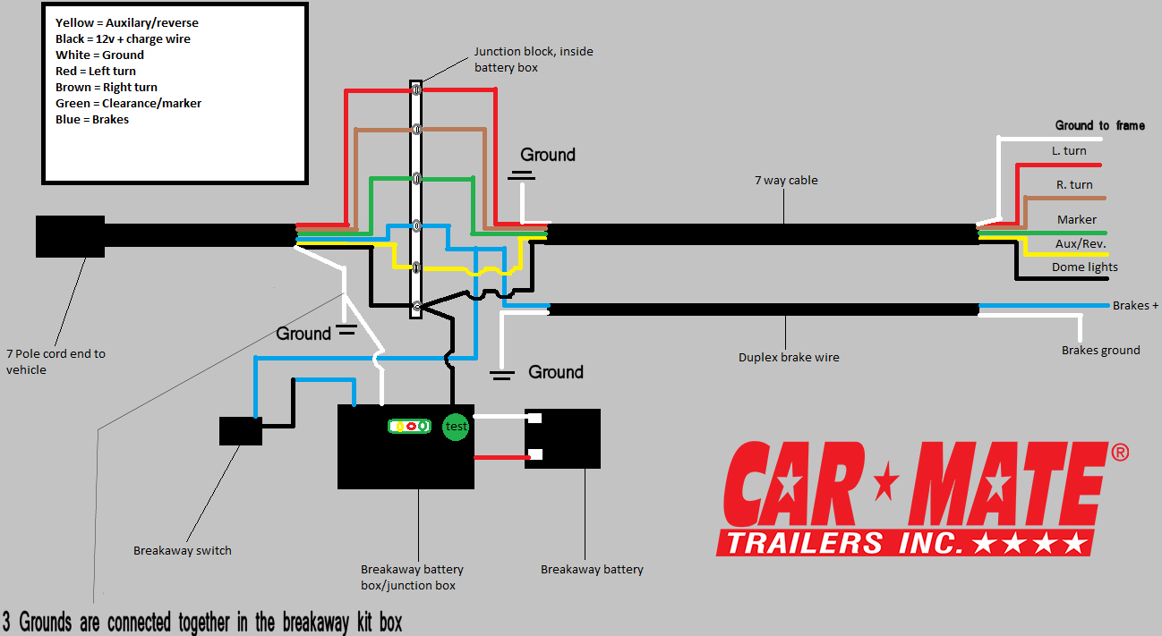
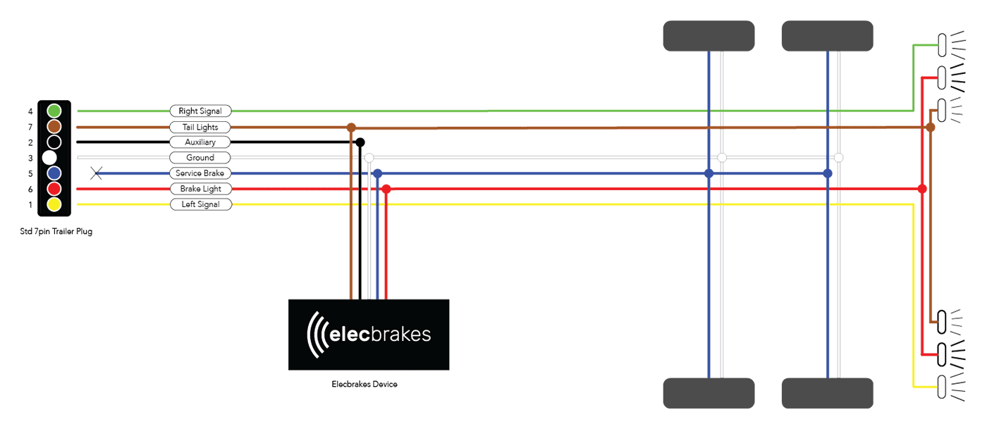
It shows the power circuits parts as easy forms, with the real power and soil links between the two as shaded sectors. 7 way plug wiring diagram standard wiring post purpose wire color tm park light green battery feed black rt right turn brake light brown lt left turn brake light red s trailer electric brakes blue gd ground white a accessory yellow this is the most common standard wiring scheme for rv plugs and the. Red 12 volt auxiliary power.
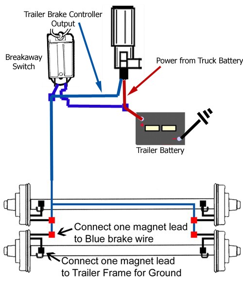
Splice one blue wire of the break away switch to the electric brake wire coming from the trailer side connector a see diagram on next page. See point b on the wiring diagram this connection will send power to the breakaway switch. A wiring diagram is a simplified conventional pictorial depiction of an electric circuit.
Tow be that cable has of tow always switch with puli tow 00 not hook to chan loop or ball with 1/4 thru with not over installed switch be to pivot. Check and install battery and charger into the battery case. Schematic wiring diagram for breakaway switch t.
Here is a wiring diagram for your trailer breakaway kit. Blue wires are interchangeable on the break away switch 3. Breakaway kit installation for single car mate trailers inc the trailer and how to replacing switch on a electric brake control wiring diagrams mirage brakes emergency wire diagram.
Wiring diagram for tandem axle trailer best breakaway kit. This guide will be talking trailer breakaway kit wiring diagram. Print the wiring diagram off in addition to use highlighters in order to trace the signal.
This little bit of schematic attaches into the full trailer wiring diagram from our other article. Trailer connectors are used between the two to allow disengagement when not towing. I also attached an install video that shows the kit installed as well as.
Breakaway kit installation for single and dual brake axle trailers etrailer com. Wiring diagram for common plugs breakaway switches. Connect one lead of the trailer breakaway switch to the breakaway batterys positive wire.
7 pin trailer brake wiring diagram for further trailer wiring diagram truck side as well as dodge ram trailer wiring diagram along with index as well as ford f trailer wiring diagram also hydraulic braking systems.how to wire. Special light and wiring systems need to be installed on your tow vehicle before you can tow any trailer. See point a on the wiring diagram connect the second wire coming out of the switch to the brake wire (blue) coming out of the battery box.
It represents the physical elements of the electric circuit as geometric forms, with the actual power and connection links between them as thin sides. The trailer lighting system must not be directly spliced into your tow vehicle lighting system. It signifies the electric circuits factors as simple shapes, using the true power and floor contacts between them as coloured sectors.
This is typical, but check your system to be sure the wires (colors) are the same. June 19 2021 on trailer brake wiring diagram with breakaway. Both wires on the breakaway switch are interchangeable.
'5 to only charge the þreakawaybattery when vehicle is running, a battery insiaäiéð in the 12 suppìy line (black wire for tow charger). The black wire from the break away switch will connect to the blue wire from the break away box, as shown in the provided diagram. Power to charge the battery comes from the “aux +12v power” wire (usually red, but sometimes black).
Power tests check & test cables and devices with regard to power inside the box you are usually working in to prevent electric shock prior to working on them. Breakaway system for 1 to 3 axle trailers w/electric brakes, includes battery box, 5 amp battery and breakaway switch. The trailer wiring diagram shows this wire going to all the lights and brakes.
Bargman breakaway switch wiring diagram splice one of the two wires coming out of the breakaway switch into the trailer brake the following diagram shows a typical wiring configuration for a hopkins. The electric circuit diagram contains the adhering to signs. 2 wire trailer breakaway switch wiring diagram source:
7 pin trailer wiring diagram with breakaway. On this page (typically below the product links) there is a helpful link section that will have the install instructions fo the hopkins breakaway kit part # 20400 that you referenced.

Trailer Wiring Diagram With Breakaway Switch Trailer

Trailer Breakaway Wiring Schematic Free Wiring Diagram

Trailer Breakaway Wiring Schematic Free Wiring Diagram
Trailer Breakaway Wiring Diagram Trailer Wiring Diagram


Trailer Breakaway Wiring Schematic Free Wiring Diagram

Trailer Breakaway Wiring Schematic Free Wiring Diagram
Technical Support Car Mate Trailers, Inc
Break Away Kit Eagle Hydraulic


Wiring Diagram For Trailer Breakaway Switch Trailer
Wiring a Trailer Breakaway Kit on a Bigfoot Travel Trailer

ENGAGER Breakaway Kit with LED Test Lights LWBKLEDE DL

Wiring Diagram For Trailer Breakaway Switch Trailer

Trailer Brake Breakaway Wiring Diagram Trailer Wiring

3 Wire Trailer Breakaway Switch Wiring Diagram Trailer

Trailer Breakaway Wiring Diagram Trailer Wiring Diagram

Trailer Wiring Diagram 7 Way With Breakaway Trailer
Trailer Brake Wiring Diagram Wiring Diagram
Trailer Breakaway Switch Wiring Diagram Trailer Wiring


Trailer Breakaway Switch Wiring Diagram Trailer Wiring