Water Float Switch Wiring Diagram
Installation scenarios might include a normally open float switch turning on a pump to empty a tank (control schematic 2), or a normally closed float. Make sure you seal the cable entrance with a cable gland.

Float switch Wiring automatic Manual singlephase water Pump Controller Water Pump YouTube
Float switch wiring automatic manual single phase water pump controller water pump youtube water level switch electrical circuit diagram water pumps.

Water float switch wiring diagram. In the past, old float switches worked by opening and closing dry contacts to send electrical signals that set off a low water level alarm. Float switch is basically is the combination of no and nc circuit that changes its contacts depends upon the alignment at which it is placed. As the liquid level goes up or down, it moves vertically with the liquid level.
The information below refers to v pumps and wiring. The 'float' part of the switch simply goes up and down. The electrical wire needs to be fixed in a position that isn’t going to change the depth of the float switch, as seen in figure 2.
Essential tips for safe electrical repairs. 12 awesome wiring diagram for 220 volt submersible pump ideas well pump submersible well pump submersible pump. A float switch consists of the floating switch and the electrical wire.
But, it doesn’t imply link between the wires. Float switch wiring ad general installation 𝐅𝐥𝐨𝐚𝐭 𝐒𝐰𝐢𝐭𝐜𝐡 𝐖𝐢𝐫𝐢𝐧𝐠 𝐃𝐢𝐚𝐠𝐫𝐚𝐦 𝐒𝐑𝐊 how to wire a tameson com switches control pilot devices cable with 3 mtrs create pump circuit tank level diagram continuous sensor did i. Injunction of 2 wires is usually indicated by black dot to the junction of two lines.
In this article, we are going to see float switch connection diagram and wiring. This circuit can be used to fill a water tank automatically. This is a simple wiring schematic showing the wiring for the float.
For example look at the chassis battery is stated as 12v 20ah. At times, the cables will cross. Float switch wiring diagram for water pump youtube home electrical wiring electric water pump solar water pump.
The first thing i did was to sketch out a simple wiring diagram showing all. Let s start with the most basic float switch. As you can see in the schematic diagram of 2 way switch circuit below the common of.
According to earlier, the traces in a septic tank float switch wiring diagram signifies wires. Single phase submersible pump starter wiring diagram on water control panel inside to. Float switch wiring automatic manual single phase water pump controller water pump youtube electrical circuit diagram water level switch water pumps.
When it goes down all the way it turns on the pump, filling the mash tun until the mash tun is filled with enough sparge water to. A float switch is a mechanical switch that floats on top of a liquid surface. The wiring of the float switch to the alarm circuit remains the homeowner's.
How do float switches work (diagram & working principle) october 20, 2016 89117 by water level controls in float switches. A guide of auxiliary contact s and it 39 s uses and working in contactor x2f motor st submersible pump. For wiring instructions, refer to the user manual, or our new float switch wiring guide.
Wiring diagram of 2 float switch for two tanks wiring diagram of 3 motors diagram guitar fender also well and septic systems diagnostics. The rising action of the float can either close (i.e., turn on) a “normally open” circuit, or it can open (turn off) a “normally closed” circuit. Float switch controlled water level controller circuit homemade projects.
Septic system installers install the alarm float switch to the inside of the septic tank. Repairing electrical wiring, a lot more than some other household project is focused on safety. In this video we can learn float switch connection with water pump and starter connectionhow does a water tank float switch work?a float switch works to dete.
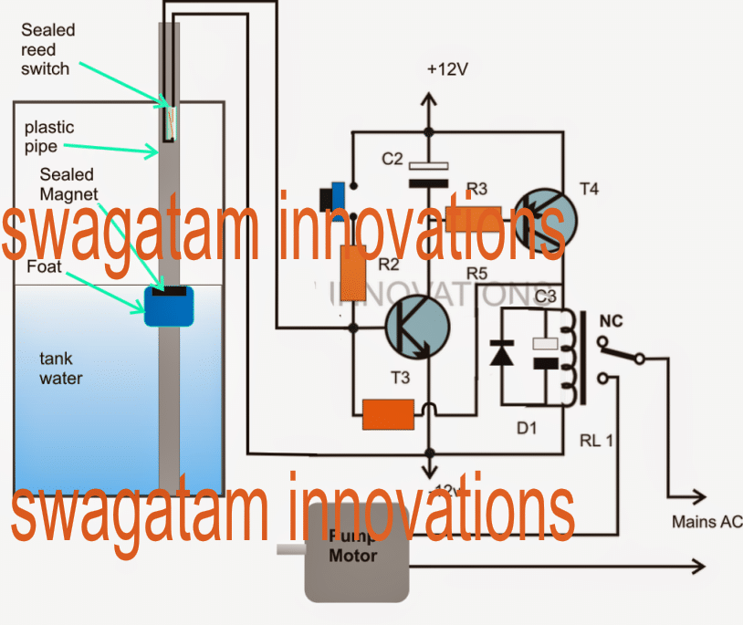
Shurflo 9300 wiring diagram for pumping into a pressurized tank submersible well pump well pump water pumps. They used magnetic reed switches that would complete the circuit once the float reaches its. The wiring or most of the switch for that matter is never in the mash water.
220v 3 wire well pump wiring diagram. Float switch installation wiring how to wire a tameson com diagram skyhooks and cable with 3 mtrs install an automatic pump controller bilge maretron equipment 9 19 eur 2m 250v 16a continuous level sensor terry love 110 220 fuel tank selector controlled water single phase. Let’s start with the most basic float switch:
Float switch controlled water level controller circuit homemade projects. In this design the switch sits a top of the mash via an adjustable plastic tube that also protects the wiring. Below is a diagram of what is described.
Once you’ve figured out the weight position and your switching levels, you’ll need to install float switch wiring to your waterproof enclosure. Shurflo 9300 wiring diagram for pumping into a pressurized tank submersible well pump well pump water pumps. It can either be fixed to a bracket on top of the water tank, or.
43 testing and analysis 62. 44 luxury single phase submersible pump starter wiring diagram submersible well pump jet pump well pump. 3 backlit bilge rocker switch wiring diagram of the three bilge pump switches the only one thats not extremely simple is the backlit automanual bilge.
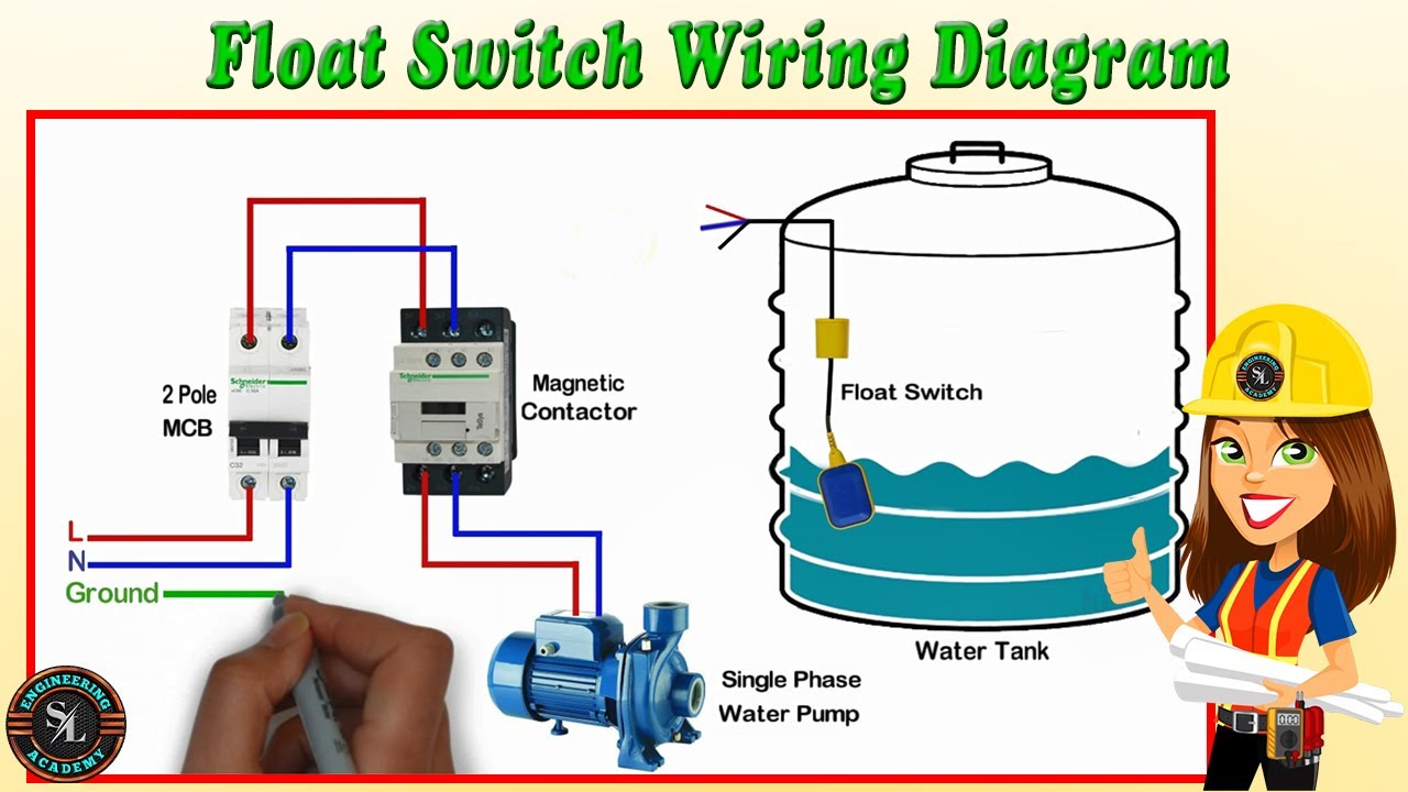
Float switch connection single phase water pumpwhat is float switch?float switch is a type of level sensor a device used to detect the level of liquid within. Float switch is basically is the combination of no and nc circuit that changes its contacts depends upon the alignment at which it is placed. 2 built in bilge running indicator.
The float switch moves with the water level in the tank and this determines when the pump turns on please note: Wiring diagram of 2 float switch for two tanks wiring diagram of 3 motors diagram guitar fender also well and septic systems diagnostics. There’ll be principal lines that are represented by l1, l2, l3, and so on.
3 wire float switch wiring diagram. Jan 24 18 02 09 pm. Aerobic septic system wiring diagram download.

Float switch Wiring singlephase water Pump water Pump changeover switch YouTube

Float Switch Installation For Water Tank Float Switch Control Diagram In Hindi Urdu YouTube

Safe & Simple Water tank Level Float Switch Wiring Diagram for Water Pump YouTube

Float switch wiring diagram for water pump using contactor in hindi YouTube

Electrical Wiring, House Wiring or Home Wiring Complete Guide

Float Switch Installation Wiring & Control Diagrams APG

float switch wiring diagram for water pump YouTube

Wiring Diagram For Float Switches Wiring Diagram Dash

🔥float switch wiring diagram for water pump🔥 YouTube

28 Septic Tank Float Switch Wiring Diagram Wiring Diagram Resource

FLOAT SWITCH WIRING INSTALLATION FOR WATER TANK! FLOAT SWITCH CONNECTION YouTube
Build A Float Switch
Float Switch Water Level Controller Circuit

Dual Float Switch Wiring Diagram For Your Needs
Septic Pump Float Switch Wiring Diagram Tank Fresh Amazing Gallery The Best Electrical Circuit

Installing float switch to bilge pump? Page 1 iboats Boating Boat wiring, Boat

Water Tank Float Switch Wiring Diagram

Water Tank Float Switch Wiring Diagram

20 New Float Switch Circuit Diagram